
The TCP Connection
- TCP is said to be connection-oriented because before one application process can send data to another application process, the two processes must first ‘handshake’ with each other before any data is transferred.
- A TCP connection provides a full-duplex service: if there’s a TCP connection between Process A on one host and Process B on another host, then application-layer data can flow from A to B at the same time as from B to A.
- A TCP connections always point-to-point (i.e between a single sender and single receiver).
- Therefore, multicasting – the transfer of data from one sender to many receivers in a single send operation – isn’t possible with TCP
How a TCP connection is established
- Let’s say a process in one host (the client process) wants to establish a connection with a process in another host (the server process).
- The client application process must inform the client transport layer it wants to establish a connection to a process in the server.
- To do this, the clients first sends a special TCP segment, then the server responds with a second special TCP segment, and finally the client responds again with a third special segment.
- The first two segments carry no payload (i.e. no application-layer data), but the third segment may cary a payload.
- Because three segments are sent between the two hosts, this connection-establishment procedure is often referred to as a three-way handshake.
- Once a TCP connection is established, the two application processes can send data to each other.
- So, if we send data from the client process to the server process, the client process begins by passing a stream of data through the socket (the door of the process).
- Once the data passes through the door, the data is in the hands of TCP running in the client.
- TCP then directs this data to the connection’s send buffer
- Note during the initial three-way handshake, both hosts agree to carve out a dedicated chunk of their memory just for this specific conversation. This is the buffer that TCP immediately drops the data into one the initial connection is made.
- From time to time, TCP will grab chunks of data from the send buffer and pass the data to the network layer.
- The max amount of data that can be grabbed and placed in a segment is limited by the maximum segment size (MSS)
- Note that the MSS is the maximum amount of application-layer data in the segment, not the maximum size of the TCP segment including headers.
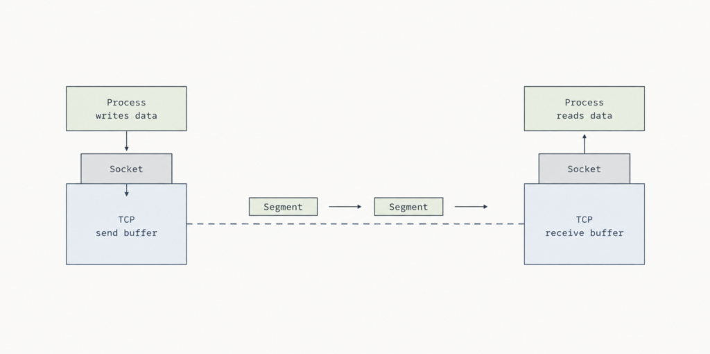
- TCP pairs each chunk of client data with a TCP header, thereby forming TCP segments.
- The segments are passed down to the network layer, where they are separately encapsulated within network-layer IP datagrams.
- The IP datagrams are then sent into the network.
- When TCP receives a segment at the other end, the segment’s data is placed in the TCP connection’s receive buffer (see image above).
- The application reads the stream of data from this buffer.
TCP Segment Structure
- The TCP consists of header fields and a data field.
- The data field contains a chunk of application data
- As mentioned above, the MSS limits the max size of a segment’s data field. So, if TCP sends a large file (e.g. image on a web page) it breaks the file into separate chunks of size MSS.
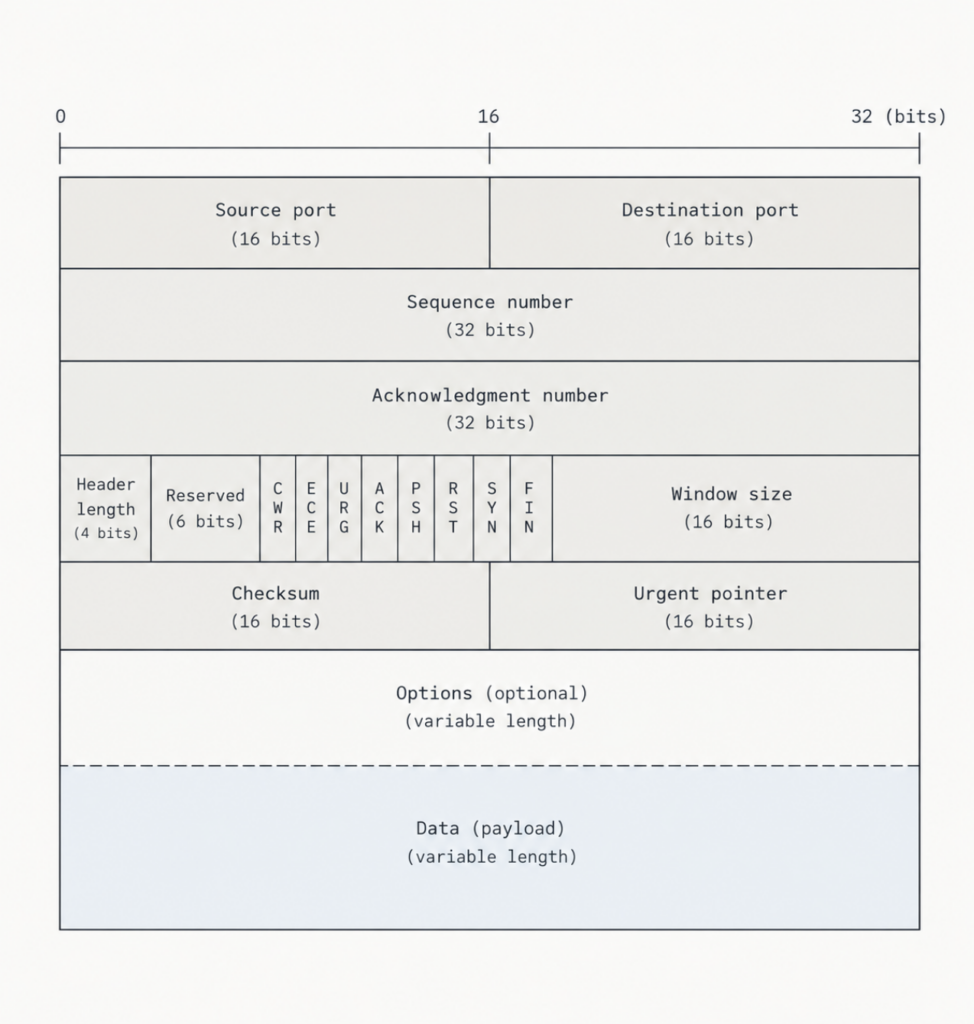
- As with UDP, the header includes source and destination port numbers, which are used for multiplexing/demultiplexing data from/to upper-layer applications.
- Also, as with UDP, the header includes a checksum field.
- A TCP segment header also contains the following fields:
- Sequence & Acknowledgment Numbers: the tracking and receipt numbers. They ensure data arrives in order and let the sender know what was successfully received.
- Receive window: the “flow control” gauge. It tells the sender exactly how much buffer space the receiver has left, preventing the sender from overwhelming it.
- Header length: simply states how large the header itself is (typically 20 bytes, unless extra options are added).
- Options: a flexible space for computers to negotiate extra rules, like the absolute maximum packet size they will accept, or adding timestamps.
- Flags (6 bits) a series of on/off switches used to signal specific events. ACK validates that this packet contains a real receipt. SYN, FIN, RST are handshake switches, used to start, end, or reset a connection. CWR & ECE are traffic jam alarms (congestion warnings). PSH & URG are commands to push data to the app immediately or mark it as urgent (though in modern networks, these are almost entirely ignored.
Sequence Numbers and Acknowledgment Numbers
- These two fields in the TCP segment header are a critical part of TCP’s reliable data transfer
- In our earlier examples (like
rdt), we numbered the packets themselves to keep track of the order the data is being sent/received: Packet 0, Packet 1, Packet 2 - TCP doesn’t do this. Instead, TCP counts the actual bytes of data inside the packet
- It views your data as one massive, continuous stream of bytes, and it labels packets based on exactly where they sit in that stream.
- So, a packet’s sequence number is simply the number of the very first byte of data contained inside it.
Imagine you’re sending a 500,000-byte file
- TCP imagines this file as a long line of individual bytes, numbered from 0 all the way to 499,999.
- The network can only fit 1,000 bytes into a single packet (this limit is the MSS). So, TCP chops your 500,000-byte file into 500 separate packet.
- Packet 1 contains bytes 0 through 999. Because its first byte is 0, its Sequence Number is 0.
- Packet 2 contains bytes 1,000 through 1,999. Because its first byte is 1,000, its Sequence Number is 1,000.
- Packet 3 contains bytes 2,000 through 2,999. Because its first byte is 2,000, its Sequence Number is 2,000.
- So, instead of saying, “I’m sending Packet 3” TCP is essentially saying, “I’m sending a chunk of data, and the starting byte in this chunk is byte number 2,000”
Mail Analogy
- Imagine you wrote a 500,000-word novel and you want to mail it to a friend.
- The post office tells you that a standard envelope can only hold exactly 1,000 words. So, you have to chop your novel up and put it into 500 different envelopes.
- Instead of numbering the envelopes “Envelope 1,” “Envelope 2,” and “Envelope 3,” you decide to label them based on the word count of the story:
- On the first envelope, you write: “Starts at Word 0.” (This envelope holds words 0 through 999).
- On the second envelope, you write: “Starts at Word 1,000.” (This envelope holds words 1,000 through 1,999).
- On the third envelope, you write: “Starts at Word 2,000.” (This envelope holds words 2,000 through 2,999).
- This is exactly what TCP does.
- The “words” are bytes, and the “envelopes” are packets. TCP does not care about counting the physical envelopes (Packet 1, Packet 2). It only cares about keeping the data in the exact right order. So, it simply stamps the envelope with the number of the very first byte inside it.
- Acknowledgment numbers are a little trickier than sequence numbers.
- Because a TCP connection allows both computers to send and receive data at the exact same time, every packet sent back and forth contains both new data and an acknowledgment (receipt) for the other side.
- The core rule for TCP acknowledgments is this: An acknowledgment number is always the sequence number of the very next byte the computer expects to receive.
Example
- Host A receives a packet from Host B containing bytes 0 through 535.
- Host A processes this data and needs to send an acknowledgment back to Host B.
- Instead of confirming the last byte it received (535), Host A determines the next sequential byte it needs (536).
- Host A stamps 536 into the Acknowledgment Number field of its next packet.
- By sending “536”, Host A is effectively telling Host B: “I have successfully received all your bytes up to 535, so you must start your next transmission exactly at byte 536.”
- If a network error occurs and Host A receives bytes 0-535, and then receives bytes 900-1000 there’s a gap (bytes 536-899 are missing).
- Even though Host A successfully received the 900–1,000 block, it will still send an acknowledgment number of 536.
- TCP only acknowledges unbroken, continuous data up to the first missing byte.
- TCP doesn’t force programmers to handle the out-of-order data (e.g. bytes 900–1,000 above) in a specific way. The system has two options:
- Discard it: delete the 900–1,000 block immediately because it arrived out of sequence.
- Buffer it: keep the 900–1,000 block in memory and wait for the missing 536–899 block to arrive and fill the gap.
- Real-world implementations choose the second option because throwing away perfectly good data forces the sender to transmit it again, which wastes network bandwidth.
- Also note: TCP connections in the real world don’t actually start from byte 0, but generate a random starting sequence number
- The reason is that if every connection started at 0, a severely delayed packet from an old, closed connection could arrive late and be mistakenly accepted as valid data in a brand-new connection between the exact same computers.
Round-Trip Time Estimation and Timeout
- TCP uses a timeout/retransmit mechanism to recover from lost segments (like we saw in rdt)
Estimating the Round-Trip Time
- To set accurate countdown timers, TCP needs to know how long the round-trip of data on the network (i.e. the route-trip time, RTT).
- To calculate this round-trip time it uses three basic rules:
- TCP measures the round-trip time by starting a stopwatch the exact moment it sends a packet into the network, and stopping it the moment the ACK receipt arrives. This specific measurement is called the SampleRTT.
- Even though TCP may have thousands of packets flying through a network at once, it doesn’t time all of them. Instead, it just runs one stopwatch at a time. Once it finishes timing one packet, it picks a new one to time, getting a fresh update about once per round trip.
- TCP will never measure the time of a packet that has to be retransmitted. It only times ‘clean’ packets that were sent exactly once.
- To estimate a typical RTT it needs to take some sort of average of the SampleRTT values (this is called EstimatedRTT).
- EstimatedRTT is a weighted average of the SampleRTT, putting more weight on more recent samples – this is natural because more recent samples better reflect the current congestion of the network.
- In statistics this average is called an exponential weighted moving average (EWMA).
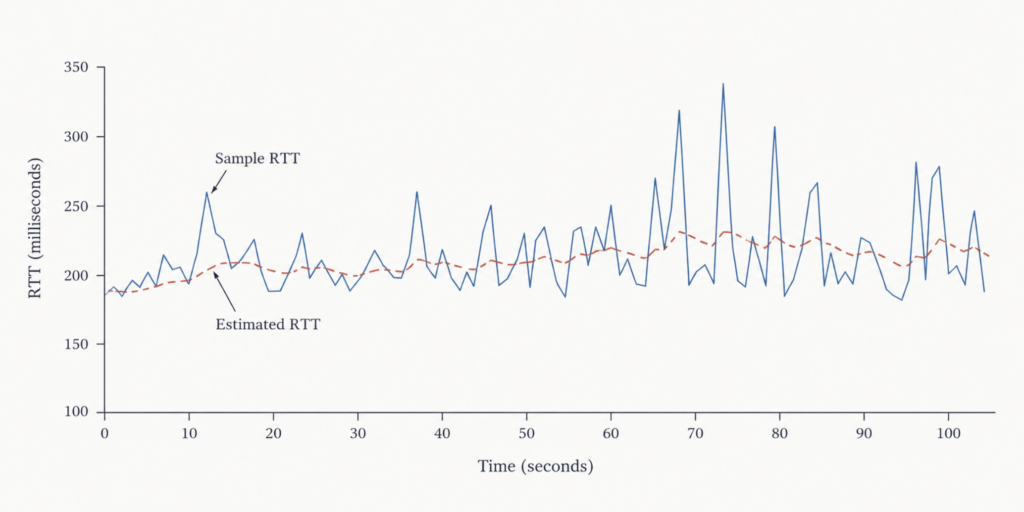
- In addition to estimating the RTT, it’s also useful to measure the variability of the RTT – this is called DevRTT, and estimates how much the Sample RTT typically deviates from the Estimated RTT.
Setting and Managing the Retransmission Timeout Interval
- Given values of Estimated RTT and DevRTT, what value should be used for TCP’s timeout interval?
- We know the interval should be greater than or equal to EstimatedRTT or unnecessary retransmissions will be sent. But it shouldn’t be too much longer otherwise there will be large data transfer delays when a segment is lost.
- Therefore, the timeout should be equal to the EstimatedRTT plus some margin – that margin being large where there’s lots of fluctuation in the SampleRTT values and small when there’s little fluctuation.
- This is the method for determining the retransmission interval:
Timeout Interval = EstimatedRTT + 4 ⋅ DevRTT- TCP also uses pipelining, allowing the sender to have multiple transmitted but yet-to-be-acknowledged segments outstanding at any given time
- The specific number of outstanding, unacknowledged segments that a sender can have is determined by TCP’s flow-control and congestion-control mechanisms.
- An initial
TimeoutIntervalvalue of 1 second is recommended
Reliable Data Transfer
- The Internet’s network-layer service (IP service is unreliable) – it doesn’t guarantee data delivery or that it will be in order.
- Because transport-layer segment are carried across the network by IP datagrams, transport-layer segments can suffer from the problems of the IP datagrams themselves.
- TCP converts IP’s unreliable, best-effort service into a reliable stream that guarantees data arrives uncorrupted, in sequence, without gaps, and without duplicates.
- Key mechanics of the TCP sender setup include:
- Single-Timer Strategy (RFC 6298): rather than running separate timers for every unacknowledged packet, TCP uses a single retransmission timer associated strictly with the oldest unacknowledged segment to minimise processing overhead.
- Three Core Sender Events:
- TCP packages the data into a segment, stamps it with the sequence number of its first byte, passes it to IP, and starts the timer if it is not already running.
- Triggers retransmissions when a packet’s delivery time expires.
- Processes incoming confirmations from the receiver to clear acknowledged data and manage the timer (ACK receipts).
Flow Control
- We mentioned above that hosts on each side of a TCP connection set aside a receive buffer for the connection.
- When the TCP connection receives bytes that are correct and in sequence, it places the data in the receive buffer.
- The associated application process will read data from this buffer, but not necessarily at the instant the data arrives (as it may be busy with some other task).
- If the application is slow at reading the data, the sender can easily overflow the connection’s receiver buffer by sending too much data too quickly.
- This is why TCP provides a flow-control service to its applications.
- Flow control is therefore a speed-matching service – matching the rate at which the sender is sending against the rate at which the receiving application is reading
- Note: this is different from congestion control, which is where a TCP sender is throttled due to congestion within the IP network itself.
- TCP achieves flow control using a dynamic variable called the Receive Window (rwnd), which represents the amount of free space remaining in the receiver’s buffer.
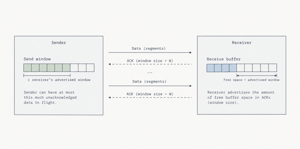
- In short, host B tells host A how much space room to has in the connection buffer by placings it current value of rwnd in the receive window field of every segment it sends to A
TCP Connection Management
- Many of the most common network attacks (e.g. SYN flood attack) exploit vulnerabilities in TCP connection management.
- How a TCP connection is managed (the three-way handshake):
- Step 1: The SYN (“synchronise”). The client sends an empty packet to the server side with a flag called SYN set to 1. The client also picks a random initial sequence number (
client_isn) to keep track of packets and places that in the sequence number field. Basically we’re saying we want to start a connection and this is the tracking number. - Step 2: The SYNACK (“Synchronise-Acknowledge”). The server receives the SYN, reserves memory space (buffers) for the new connection, and sends a reply back. It acknowledges the client’s number by replying with
client_isn + 1. It then picks its own initial sequence number (server_isn) and puts it into the sequence number field of the TCP header. Basically we’re saying we got your request and we’ re ready, here’s my starting tracking number. - Step 3: The ACK (“Acknowledge”). The client receives the server’s reply, sets up its own memory space, and sends one final confirmation packet. It confirms the server’s number (
server_isn+ 1). The SYN bit is turned off (0) because the setup phase is over. And crucially this packet can now carry real data (like requesting a webpage). Basically we confirm the connection send some data.
- Step 1: The SYN (“synchronise”). The client sends an empty packet to the server side with a flag called SYN set to 1. The client also picks a random initial sequence number (
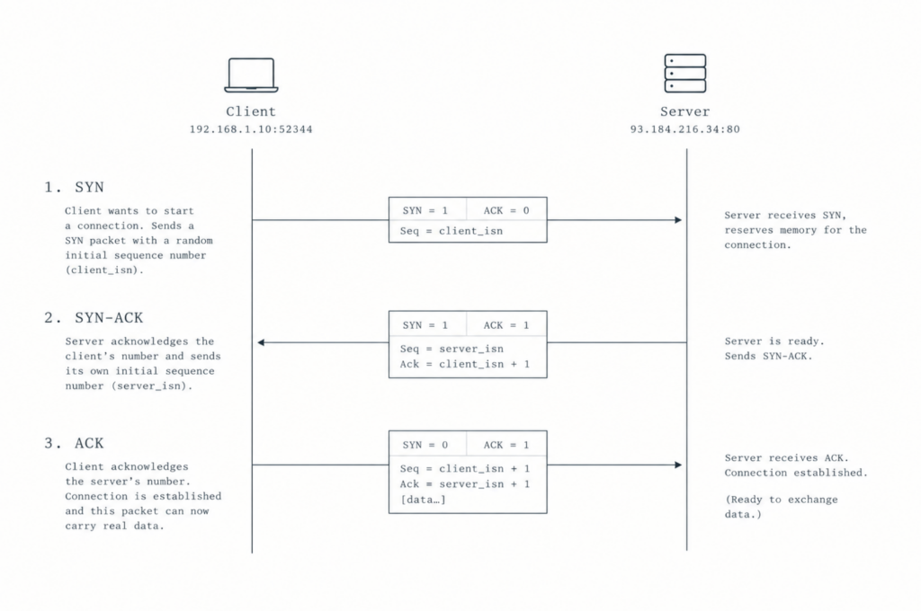
- As the TCP client needs to wait to receive a SYNACK message from the server before it knows it has accepted the connection, you might think that a one RTT delay is necessary in the handshake protocol.
- But, if the client and server have previously communicated, it’s possible to use a technique known as “fast open” (also known as 0 RTT) to reduce the handshaking time to zero.
- In other words, a client can immediately send data to a connection-oriented server with which it has previously communicated without undertaking the first two steps of a traditional 3-step handshake.
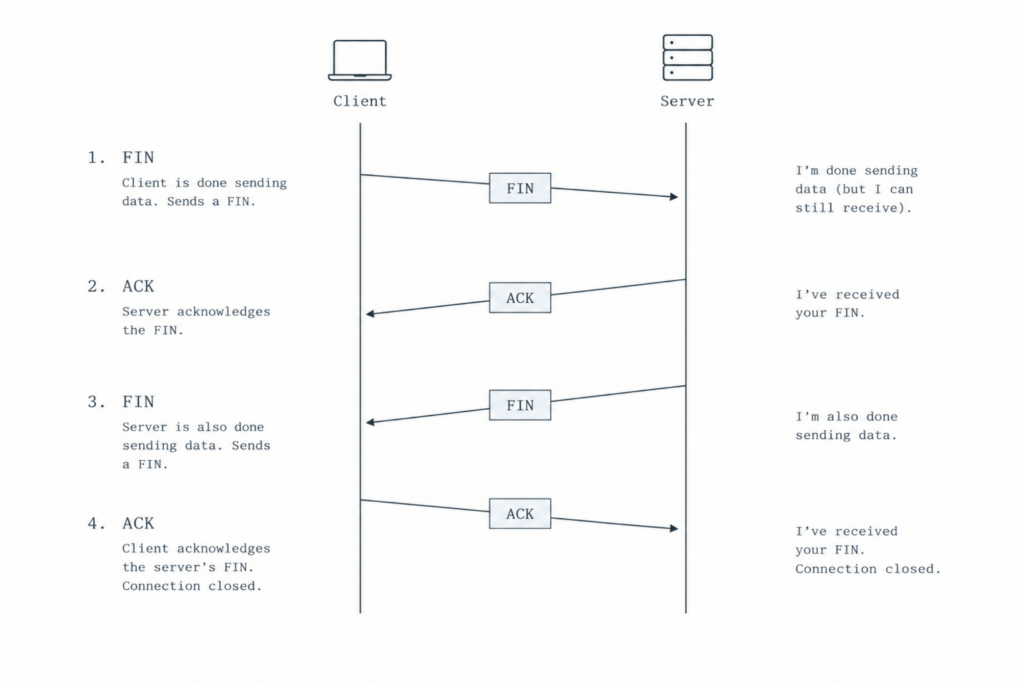
- When a connection ends, the “resources” (that is, the buffers and variables) in the hosts are deallocated.
- Either host can initiate a close. If the client closes first:
- Client sends
FIN: “I’m done sending data.” - Server sends
ACK: “I got your request to close.” - Server sends
FIN: “I’m also done sending data.” - Client sends
ACK: “Got it.”
- Client sends
- Once finished, all allocated memory on both hosts is freed.
- During connection setup, the client TCP moves through three specific states:
CLOSED: The starting state (no active connection).SYN_SENT: The client has sent its initialSYNpacket and is waiting for the server’s reply.ESTABLISHED: The client received the server’sSYNACKconfirmation; the connection is now live and ready to send application data.
SYN Flood Attack
- As we’ve seen, in a TCP three-way handshake the server buffers in response to receiving a SYN, sends a SYNACK in response, and waits for an ACK from the client.
- If the client does not send an ACK to complete the connection, eventually (often after a minute or more) the server will terminate the half-open connection and reclaim the allocated resources.
- This TCP connection management protocol is how a classic Denial of Service (DoS) attack is done (also known as a SYN flood attack).
- In the attach, the attacker sends a large number of TCP SYN segments, without completing the third handshake step.
- With the deluge of SYN segments, the server’s connection resources become exhausted as they are allocated (but never used) for half-open connections. Legitimate clients are then denied service.
- SYN flood attacks were among the first document DoS attacks, and still constitute about 14% of all DoS attacks.
- Fortunately, an effective defense – SYN cookies – are now used in most major operating systems.
- SYN cookies work as follows:
- When the server receives a SYN segment, it doesn’t know if it’s coming from a legitimate user or part of a SYN flood attack. So instead of creating a half-open TCP connection, the server runs a fast math formula (a hash) using the client’s IP address, port number, and a secret key to generate a unique sequence number (the cookie). It sends this cookie back to the client in a
SYNACKpacket and immediately forgets the interaction ever happened. - A legitimate client will reply with an
ACKpacket, echoing back the cookie (plus 1). When the server receives thisACK, it doesn’t look up a saved record (since it didn’t save one!). Instead, it re-runs the math formula on the spot using the incoming packet’s IP and port. If the math checks out, the server knows it’s a real connection so now allocates memory and set up the socket. - Attackers sending fake requests never send that final ACK back. Because the server never reserved any memory in step 1, the fake requests do zero harm and the server’s memory remains completely untouched.
- When the server receives a SYN segment, it doesn’t know if it’s coming from a legitimate user or part of a SYN flood attack. So instead of creating a half-open TCP connection, the server runs a fast math formula (a hash) using the client’s IP address, port number, and a secret key to generate a unique sequence number (the cookie). It sends this cookie back to the client in a